|
So, I decided to get back into RC trucks again and, without knowing about the crawling craze, I bought a TLT-1.
While I was building my stock TLT, I came across www.rccrawler.com and
I was thoroughly amazed at what a TLT could be made into. After reading the forums, I was inspired to make my own
crawler and I found all the info I needed to select the parts for my TLT build...
(3-5-2006)
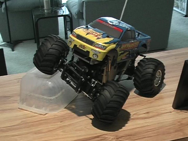
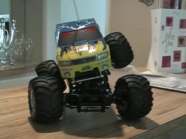
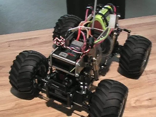
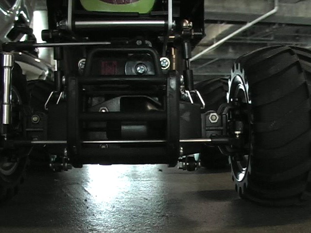
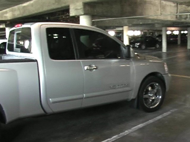
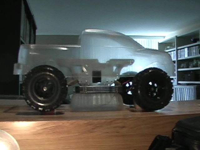
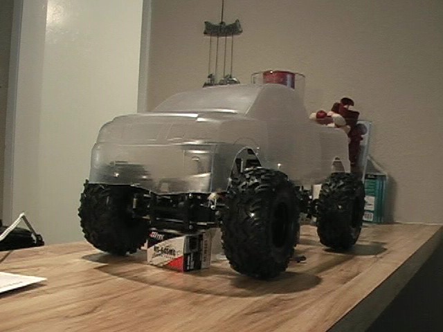
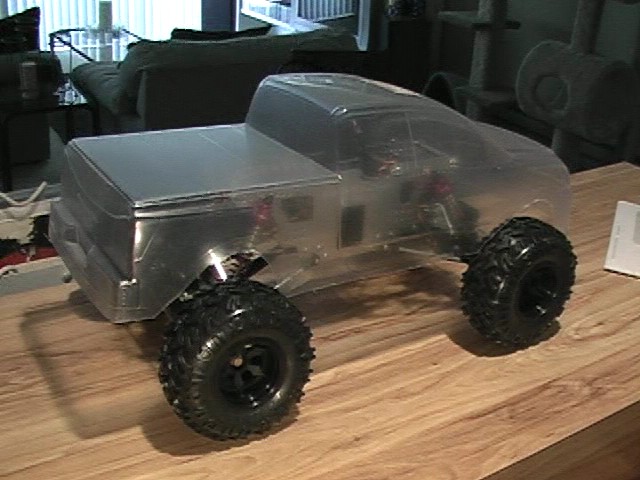
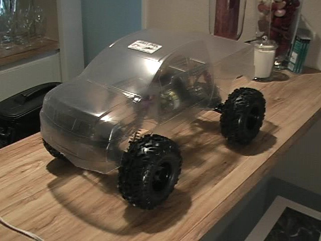
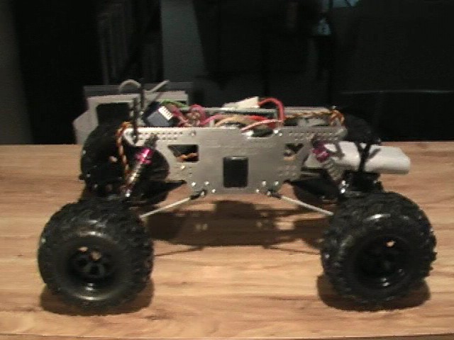
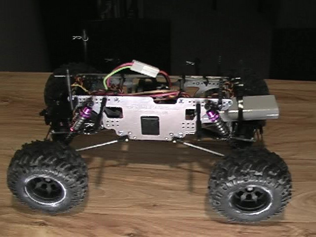
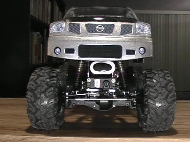
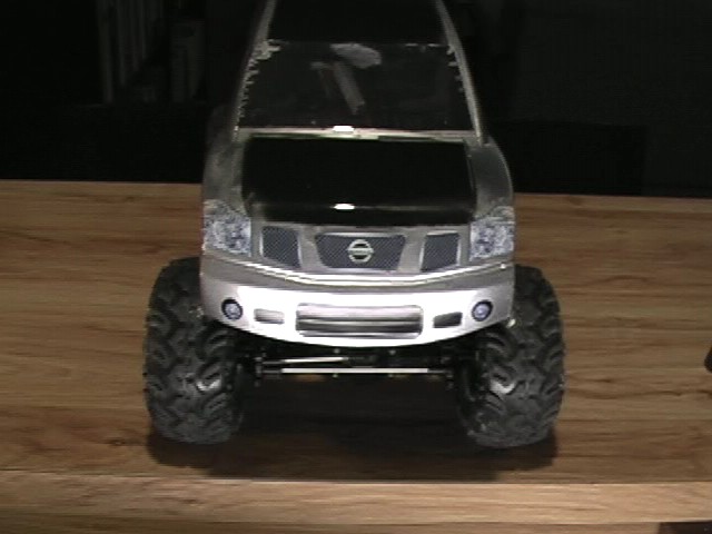
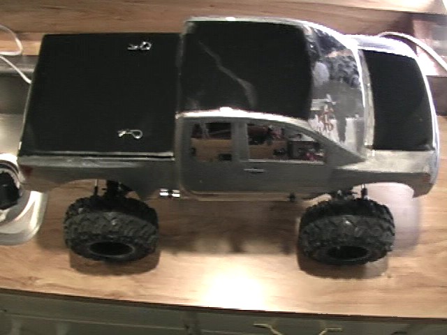
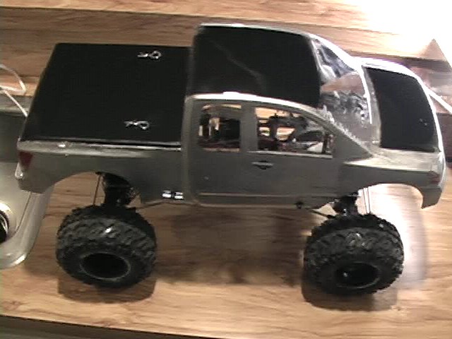
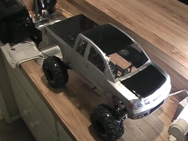
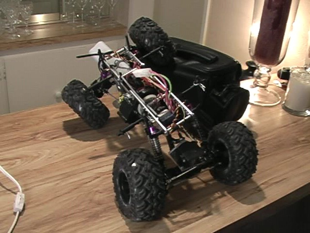
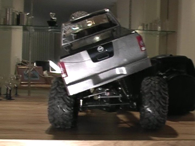
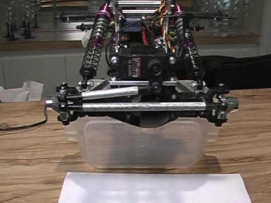
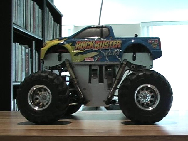
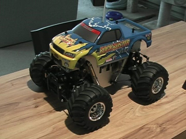
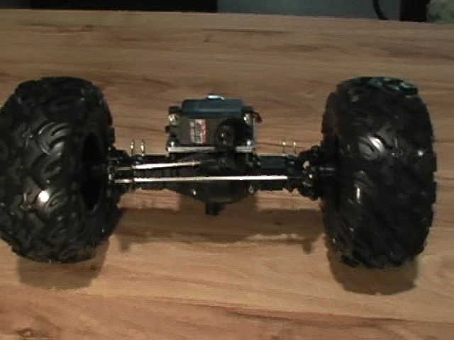
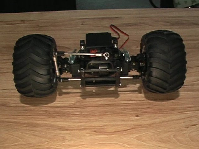
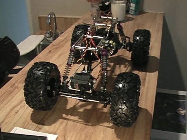
So here is my (mostly) stock TLT. The only thing arguably not stock is the 27 turn double motor, 16 tooth pinion,
and 4 wheel steering. (click to enlarge)
 looks like the box?
|
 lighting sucks
|
|
|
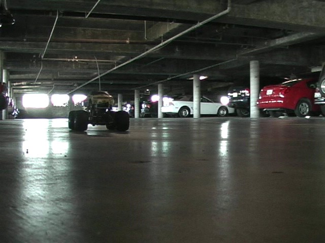
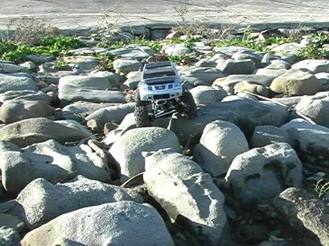
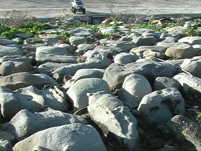
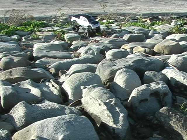
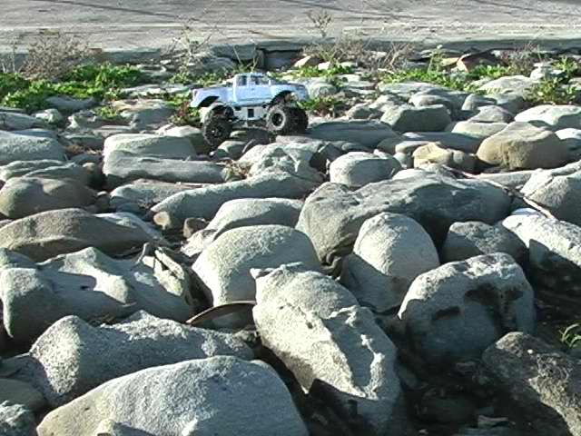
Couple of videos...
You can see how squirly this thing is with the 4 wheel steering; It is a pain to control. You can also make out a
slight torque twist. That is something that I figure I will have to work out with the crawler. (You may have to wait a few
minutes for these to load.)
(3-10-2006)
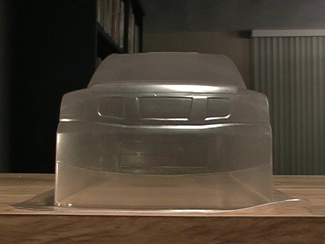
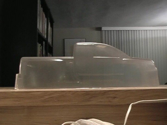
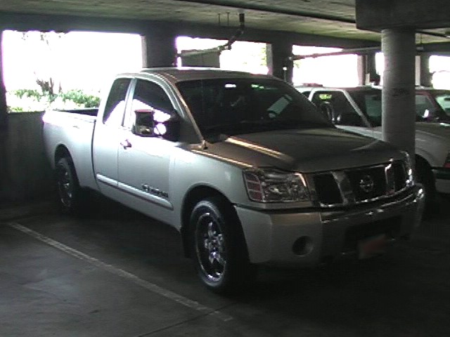
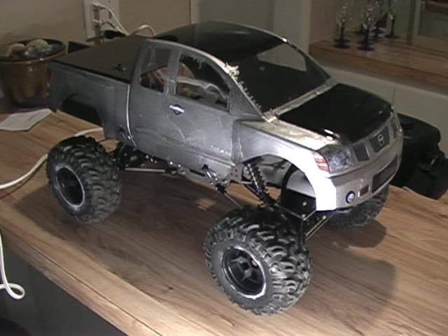
For the body of the crawler, I decided to go with a Titan... to match my truck :)
Here are the parts that I currently have...
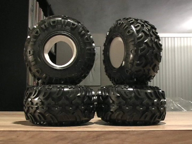 Moab 2.2
|
 HPI spikes
|
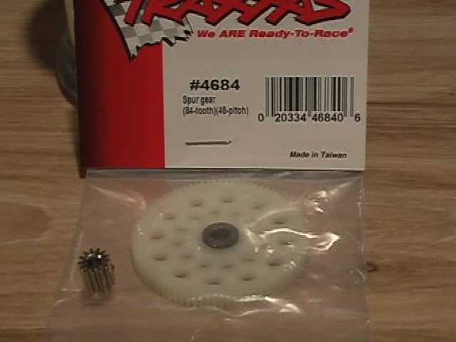 13t pinion / 84t spur
|
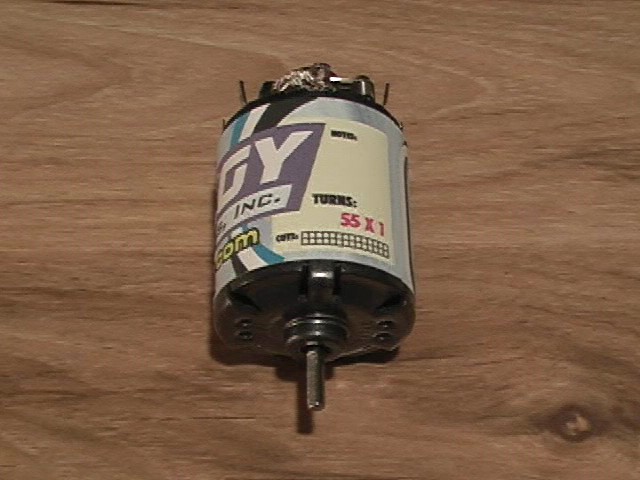 Integy 55 turn
|
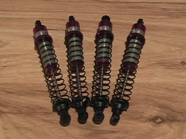 103mm aluminum threaded
|
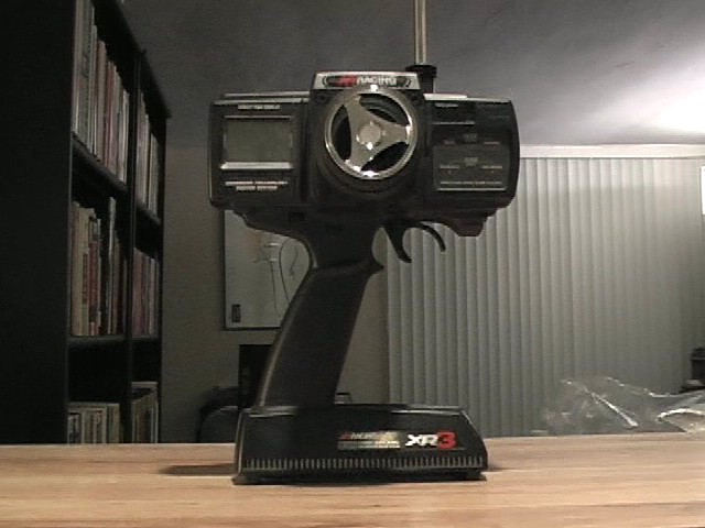 3ch JR XR3
|
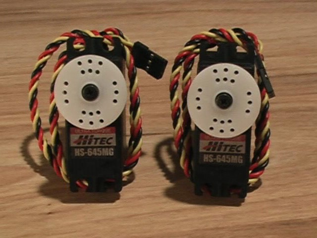 Hitec HS-645
|
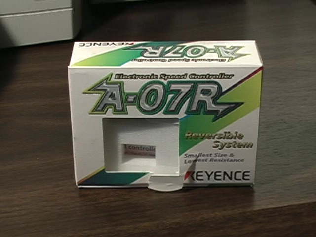 esc - currently in TLT
|
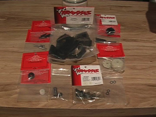 Pede tranny
|
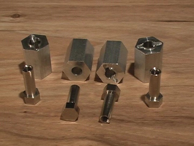
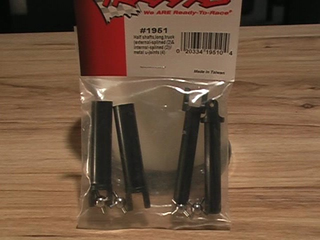 Slider shafts
|
 Metal yokes
|
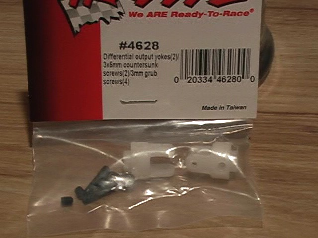 Plastic yokes
|
 Wideners
|
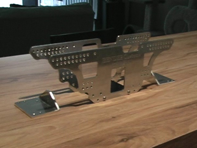 Benders
|
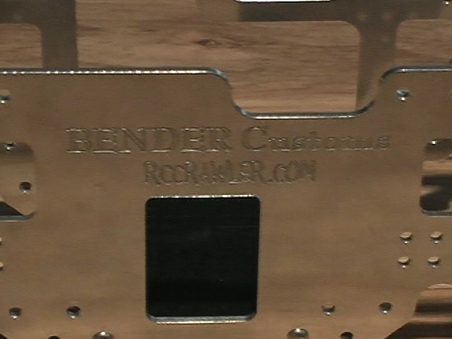 Benders
|
| And all the parts from the stock TLT. Axles, hardware, etc... |
|
(3-17-2006)
Once I get the chassis from www.BenderCustoms.com, I will start
building the crawler :) I am also going to try to makemy own links out of 6/32" threaded rod and 1/4" aluminum tubing.
Oh ya, I need to purchase those (I guess a trip to the home depot). Also gonna lock diffs with JB weld. Man, I cant wait.
I have been sitting on these parts for a week :)
(3-26-2006)
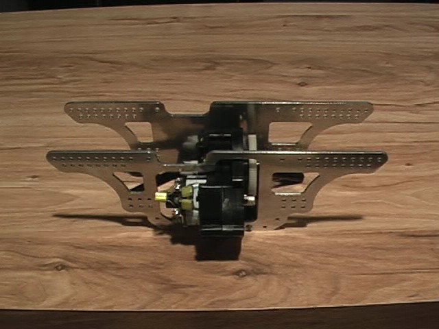
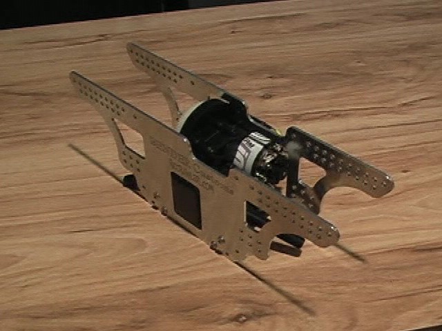
Whoot !! the chassis came in on friday (thanks Brad).
I built the tranny and attached it to the chassis.
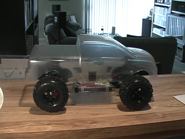
Then I did a quick mockup of the truck. I slapped the moabs on the TLT axles and roughly cut out the Titan body.
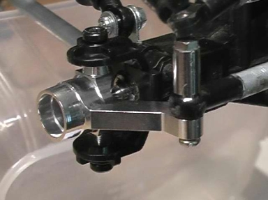
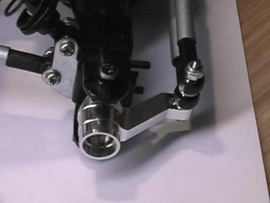
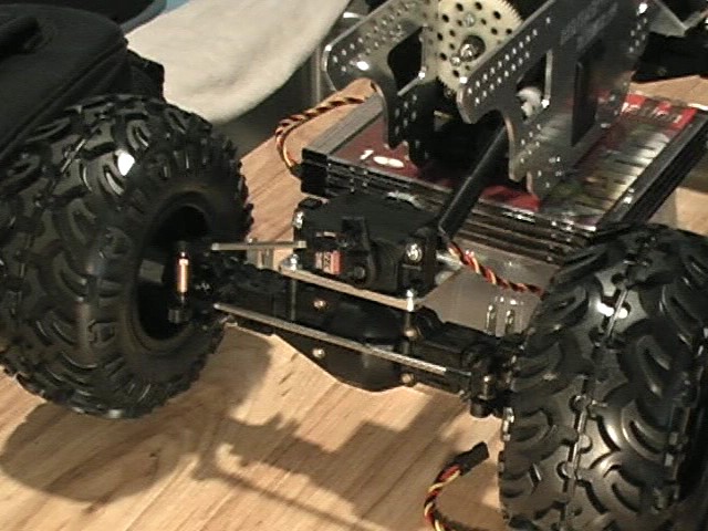
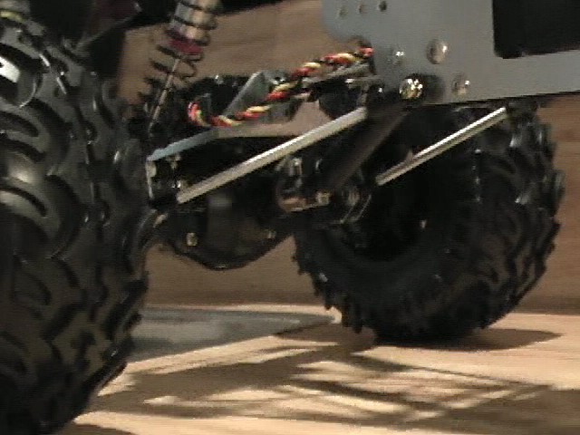
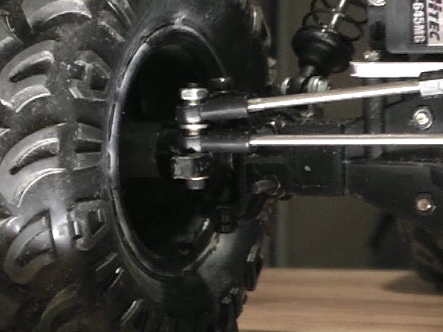
Built the axles next. (Side by side comparision of built axle and stock axle.)
 Link mounts moved to top of axle. Steering rod moved to top of knuckles.
|
 Stock axle.
|
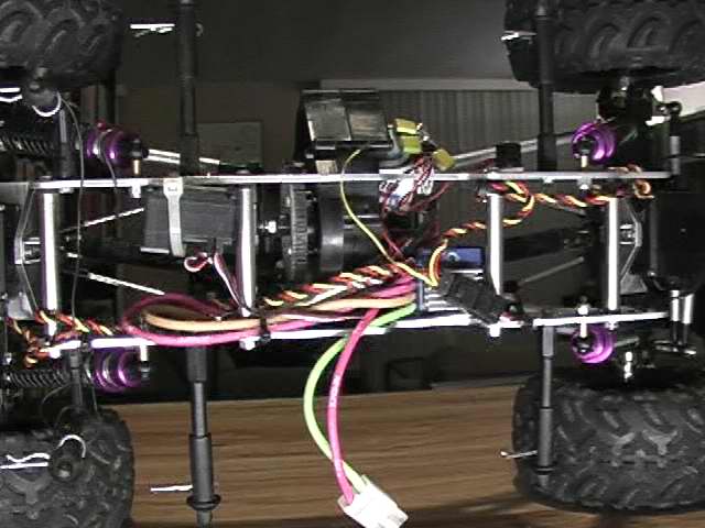
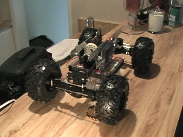
Positioned the axles and chassis to get an idea of heigth and wheel base.
 Left side
|
 Front
|
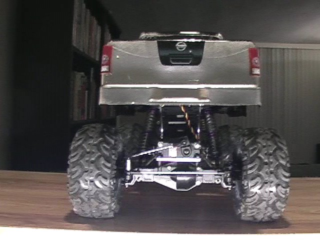
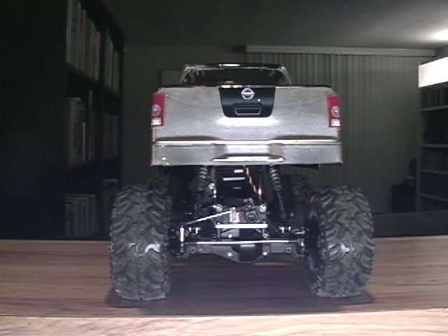
 Rear
|
 Rear
|
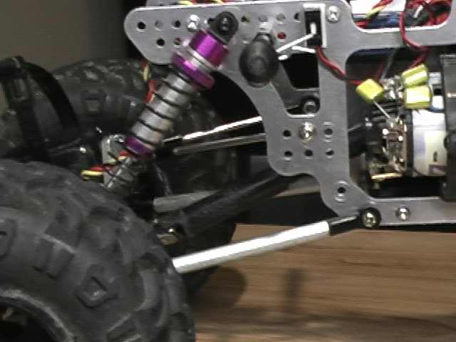
I used the bottom links from the TLT for the top links of this crawler. Then I used 6-32 steel threaded rod to make the
lower links (105mm eye-to-eye). I had to drill out the link ends a little bit to screw the rod in. I also want to use aluminum
tubing to cover the links. I tried to pick the tubing up at home depot, but they didn't carry any. The springs on the shocks
are pretty stiff, but, because the shocks are threaded, I was able to move the spring stop farther up the shock. This really
softened up the shock and allow the axle to flex alot easier. (also using 40wt oil.) The slider shafts barely meet. They
probably have about a 1/4 inch of mating. With all the links hooked up, there is no axle sway and they seem to hold the
shafts together. I wonder if the shafts would break or shear off during a high load.
Here are some stats:
- Wheel Base: 12.00 inches
- Chassis Clearance: 3.50 inches
- Differential Clearance: 1.38 inches
- Width (outside wheel): 10.75 inches
- Weight (with electronics and battery): 5.00 pounds
|
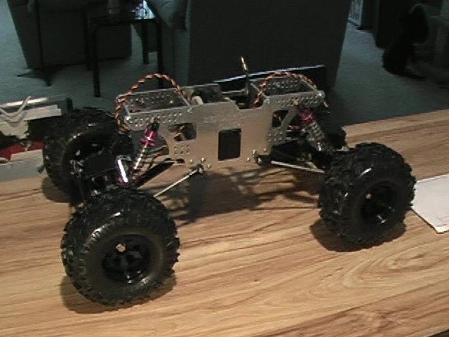 Right side
|
 Right side
|
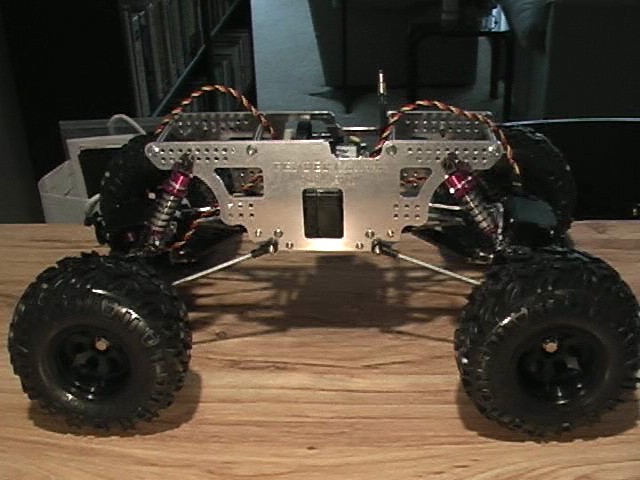
 Front
|
 Left side
|
 Top
|
 Rear diff
|
 Rear diff
|
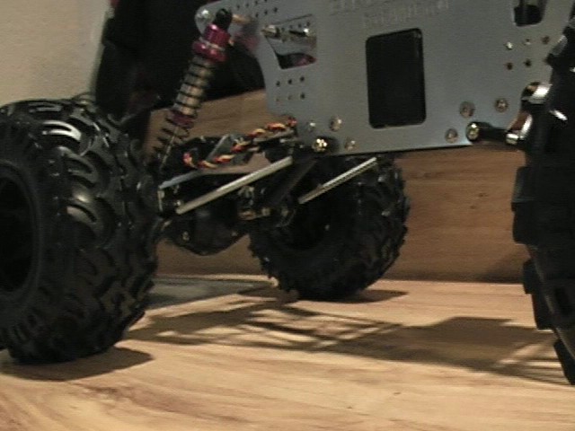
 Front flex
|
 Front flex
|
 Front flex
|
 Rear flex
|
 Rear flex
|
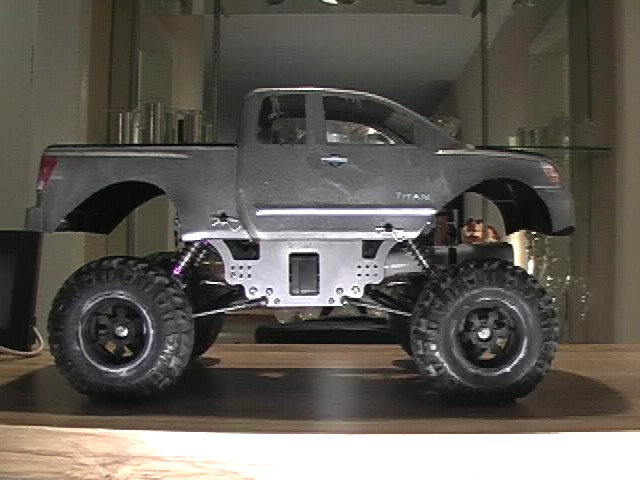
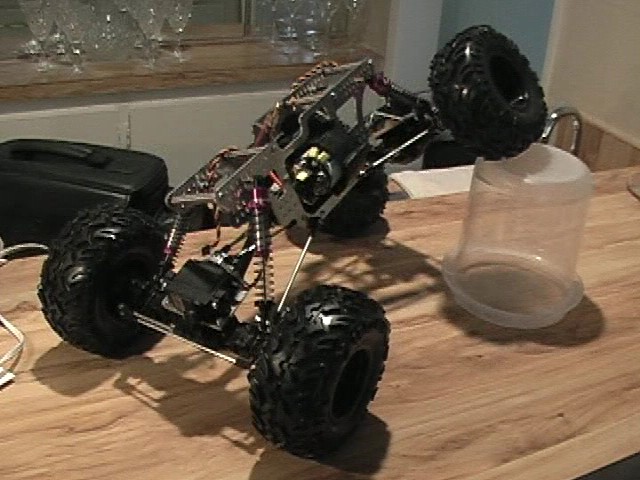
Checking the position of the body. I am going to have to figure out how to mount the body. I will probably have to mount it
farther up off the chassis or cut out the bottom of the body so the wheels will clear. (or maybe a combination of the two.)
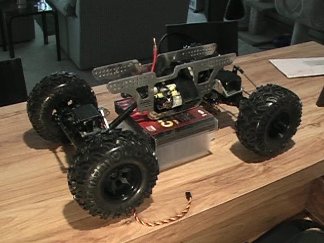
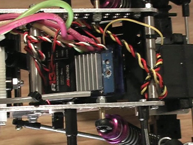
I put in the electronics and battery. Not sure if you can see from this pic, but the ESC is sitting above the chassis. I am
thinking that is a poor location on the truck since rolls overs will be common. With the body posts and the body on, the ESC
would be better protected, but I am not sure at this point.
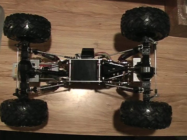
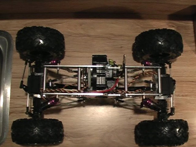
Pics of the bottom
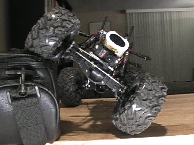
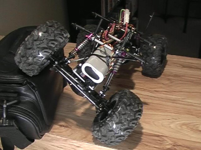
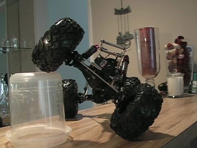
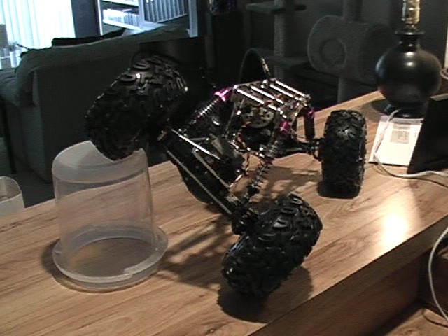
I charged up a battery and took it for a little test run. I ran the truck up the side of a desk (pics below) and it flexed pretty well.
The shocks still allow for more travel then what the pics show below, but the truck is unable to compress them further. I may have
too much oil in the shock which may make full compression of the shock difficult. I also think I could move the spring ends a little
bit further up the shock (2-3mm maybe). If that doesnt work, then I could lay the shocks down father. As the truck runs now, there
is very little torque twist, but if I moved the shocks, I may get more twist. I suppose I could go to a weaker spring. Also, with the
battery zip tied to the front servo, the battery rubs the chassis during articulation. I wonder if that is limiting the shock compression
as well.
|
|
I had some JB weld on order, but, in my excitement, I decided to use hot glue to lock the diffs (I have heard that it works).
Well, let me clear up any question that you may have about hot glue.... ahem.... IT DOES NOT LOCK THE
GEARS !!!! It was solid for about 5 minutes of run time, then I started to notice a rear wheel slipping, then a front wheel.
The center diff, however, is still locked. The hot glue actually makes the diffs act kinda like a limited slip differential. It will slip,
but it takes quite a bit of force to do so.
In addition to taking apart the axles to lock the diffs (for real this time), I also need to cut the foams and mount the tires.
Then I will need to cut and paint the body and then mount it. I am also wondering if I should lower the truck a little... maybe
down to 2.75-3.00 inches. I don't dare extend the wheel base any farther due to the shafts barely mating as it is. I would
have to figure out another shaft alternative to do so.
Overall, I am thoroughly impressed with this truck. It climed over stuff very well (when all the diffs were locked) and it
is able to turn much better than I thought it would. It has 4 wheel steering by spliting the one steering output to both the
front and rear servos. Also, the top speed is around 4-5 mph. It has alot of low end power and it is punchy and it gets up
to speed pretty quick.
More to come....
(3-31-2006)
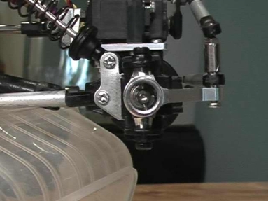
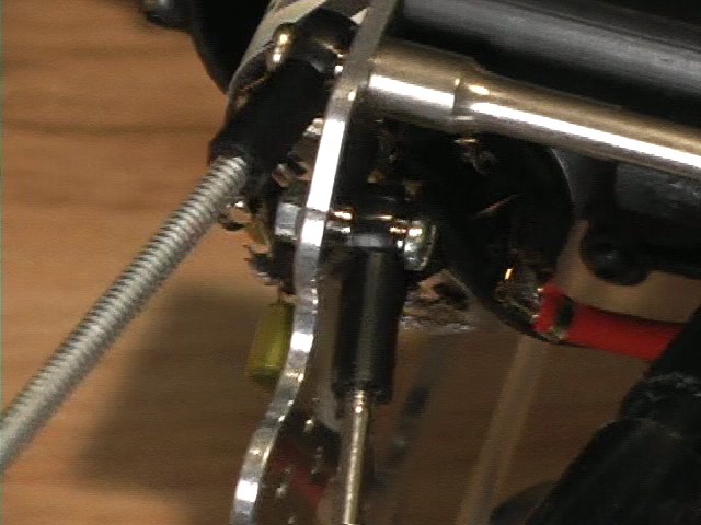
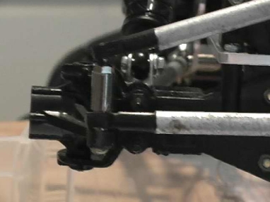
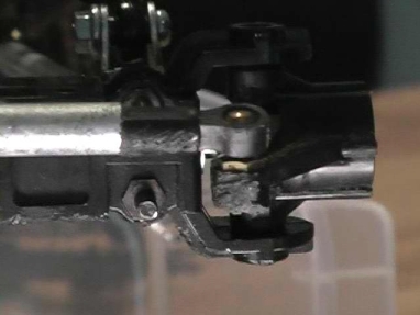
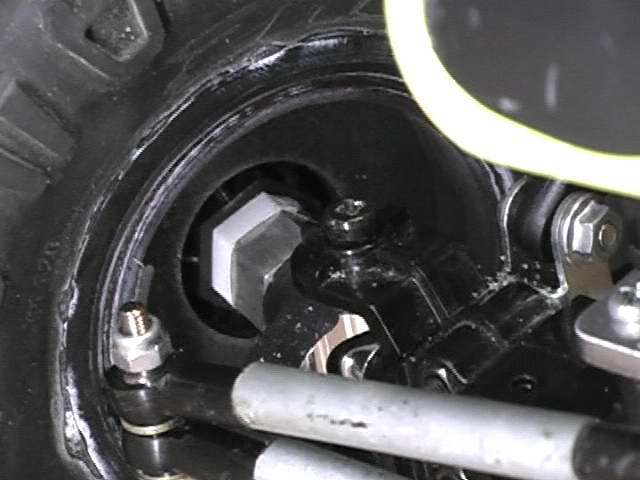
I got some JB weld this week so I took apart the axles and welded up the diffs (JB weld is pretty cool). I then put
every thing back together and took it for a little test run. Now that all the diffs were locked, I tore a screw out if the
front knuckle that was holding the steering linkage. So (to quote a sig I saw off of rccrawler.com), "If it is broke, modify
it." I made it stronger by using a screw and a nut instead of just screwing it into the knuckle.
 Stronger now
|
After I got the steering problem fixed, I ran the truck around the house noticed that the suspension was flexing poorly.
I took off the wheels, flipped the truck upside down and tried to isolate any binding. What I found was that the upper links
were dragging against the nut that I used to hold the link to the chassis. I also found that the screw and bolt that was holding
the link to the servo plate was sqeezing the links too hard. So...
 Nut on outside of chassis now
|
 Longer screw and lock nut
|
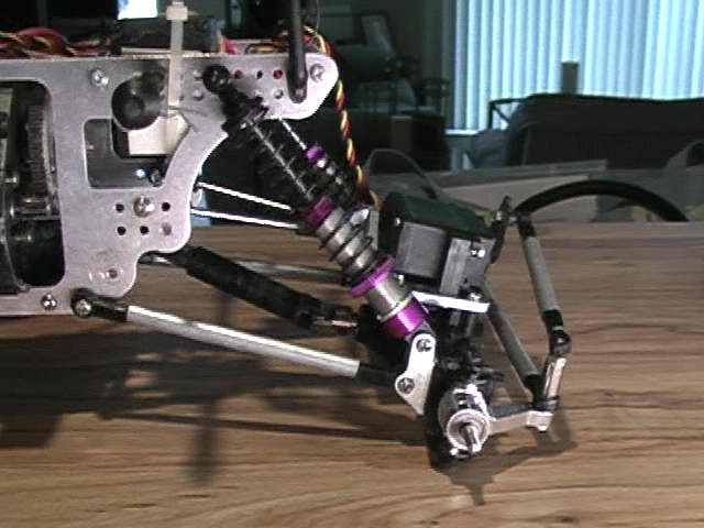
Now that the binding was fixed, I was getting a good deal of articulation. However, the truck now would roll over very
easily. So, I decided to lower the truck by moving the shock positions. On the SW2 chassis, I moved them up one hole and
in toward the center of the chassis by one hole. This lowered the truck by 0.5 inch and extended the wheelbase by 0.25 inch.
Heh... now, I couldn't place the electronics back in the same location because of the shock screw. So I took the stock TLT
battery tray and rigged it to hold the ESC and reciever and placed it at the rear of the chassis.
 Screw/nut at bottom; zip tie at top
|
 Attached to tray with double sided foam tape
|
Now, with the wheelbase extended just 0.25 inch, the pede shaft sliders didn't have enough bite to hold together
properly. They would also wobble and bind up. So, I bought another set of pede sliders and fab'ed up new drive shafts.
I cut the yoke end of the inner shaft off and then trimmed down one of the outter shafts by 0.75 inch. I then glued the
inner shaft into the cut outter shaft and left 1.0 inch of the inner shaft extended out the end. With both ends of the
drive shafts slid together and placed on the truck, this gave about 0.5 inch of bite and enough room for the shafts to slide
together when the suspension is fully compressed.
 Can be fab'ed to various lengths
|
I then cut the foams into a star pattern and mounted the tires. This gave the sidwalls more flexability than the full foams and allows the tread
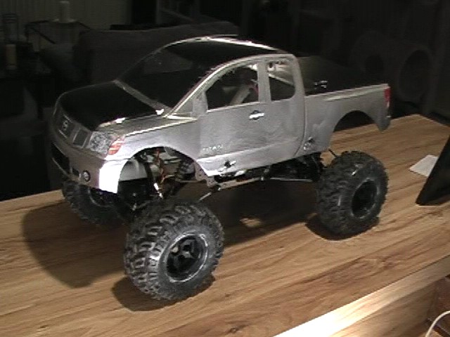
of the tire to flatten down over terrain. So, here we have the complete chassis (barring any breakage and/or modifications :) )
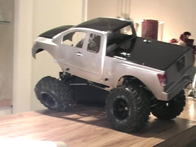
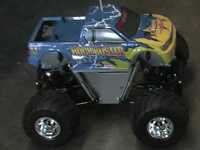
Next, I preparred the Titan body by trimming it all out, cutting the mount holes, and masking it for painting. I went with a 2-tone
paint scheme. I painted the darker color first and then the lighter. However, I am very dissapointed in how the painting turned out.
The masks didn't hold well at all. I got the the 2 colors bleeding into each other and running all over the place. I salvaged it as best
I could, but I think it still looks like crap. I consider that a learning phase and, now, I know what not to do. I ordered a new body
anyway :)
Here are the stats on the "finished" truck:
- Wheel Base: 12.25 inches
- Chassis Clearance: 3.00 inches
- Differential Clearance: 1.38 inches
- Width (outside wheel): 10.75 inches
- Weight (with electronics, battery, and body): 5.40 pounds
|
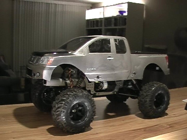
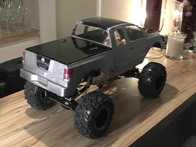
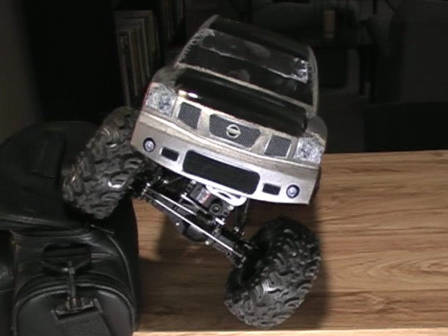
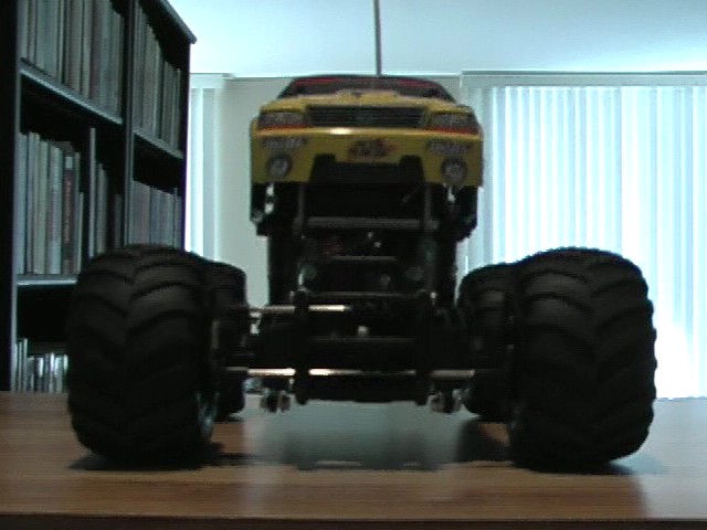
I wonder if the body looks too high on the chassis, but, at this heigth, the tires barely rub the body. Here is one spot it does rub.
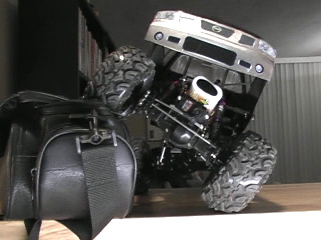
Here is a set of flex pics with and without the body. (Camera bag is 7.00 inches tall.)
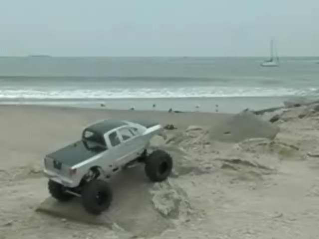
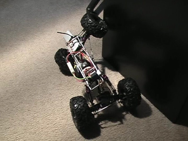
Even though it was 7pm and dark outside, I couldn't wait any longer to run the truck on some rocks and stuff. I charged up a
battery and headed outside my apartment. I ran it up this rock-framed planter area with thick low cut grass/bush things. I was amazed
at how well it performed and rolled over most everything. I found a 3 inch drainage pipe that had water erosion around it which created
a 6 inch deep by 12 inch wide crevasse. The truck dipped in and powered up right out of it. It was great... not once did it roll over ! :)
I am going to have so much fun with this truck.
On a 15 minute charge, I was still running the truck after 30 minutes, but I decided to go back inside when it started to rain. I am
curious to see how long a single charge will last.
I will post some videos when I get a chance (and when it is not raining).
(4-08-2006)
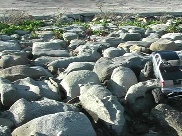
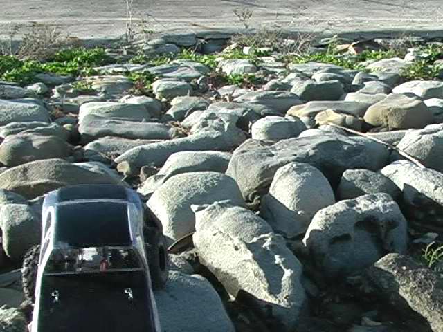
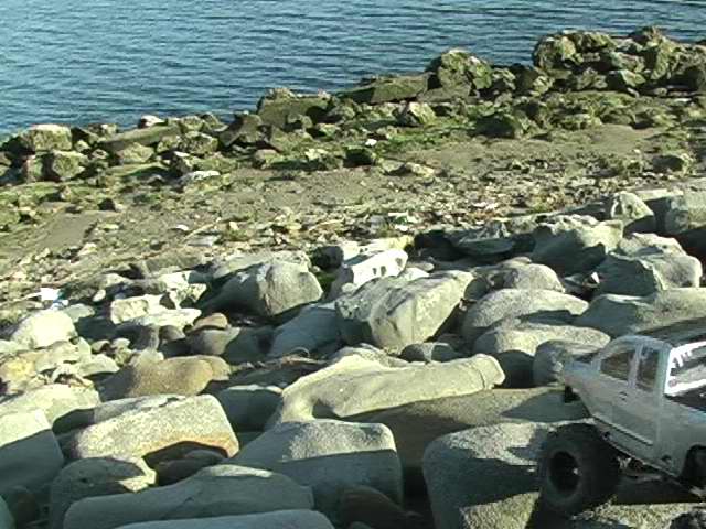
Whoot! I have got some more drive time in. Right outside my apartment, there is small river that dumps into the ocean
and I have been able to run the truck on the rocks that line the river bed. From this drive time, I have found some weaknesses
on the truck. I have had to replace many of the nuts used on the truck with lock nuts (I kept having the screw to the upper
links fall out and then the links drop to the ground). I also noticed that the steering links kept getting whacked on the
rocks and the lower links bending a little. So I bought some brake line and sleeved the steering links and the lower links.
After sleeving the steering links, however, they now hit the axle which prevented the full steering. So I had to move the steering
link to the outer hole on the steering arm. You can also see how chewed up the axles, drive shafts, and links are getting from
dragging on the rocks.
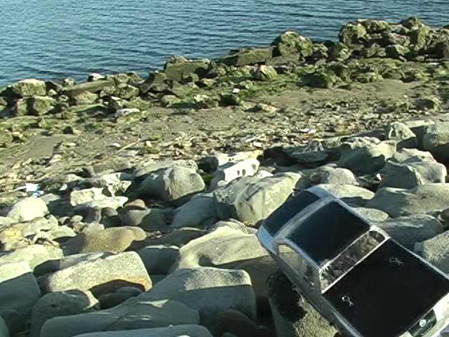
On to the videos !!! (If these videos do not play using quicktime, you can right click on the links and click "save target as.." to
download them to your computer. They will run using windows media player.)
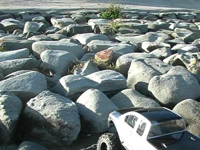
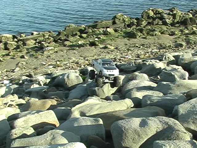
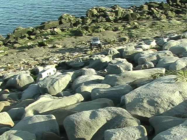
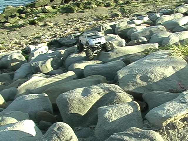
Here are 4 attempts trying to get over this one rock set. (Note: the slope of the river bed (and the rocks) is about 30 degrees.)
Trying to go up that same rock set.
3 various climbs
A couple of descents
3 more climbs
(4-28-2006)
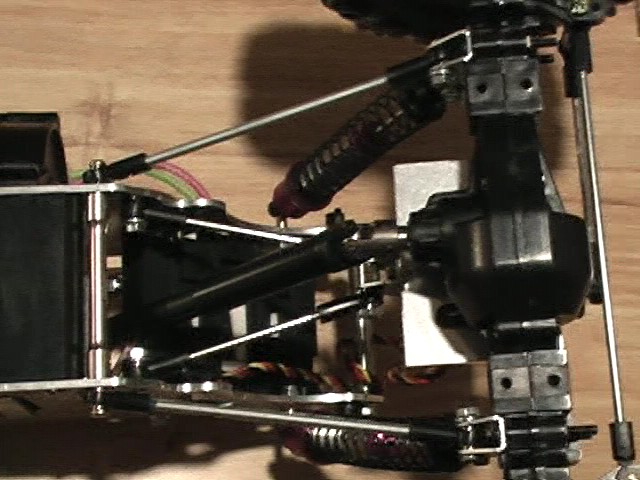
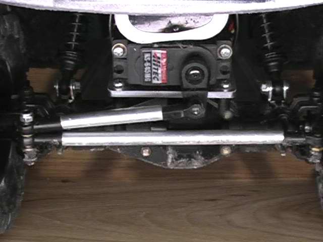
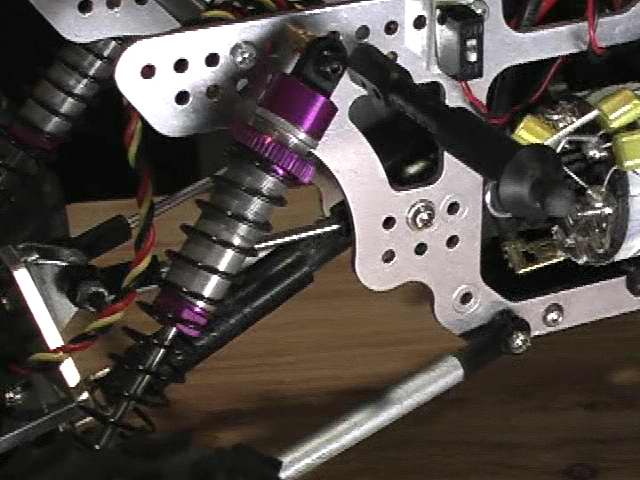
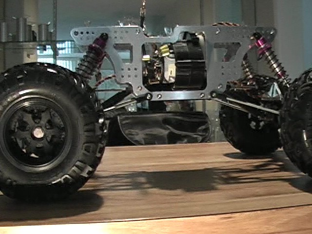
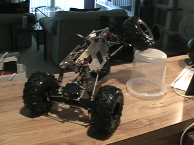
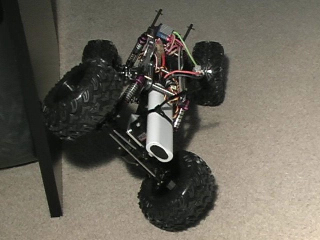
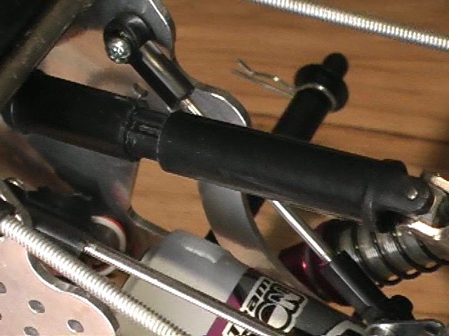
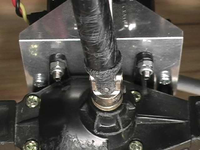
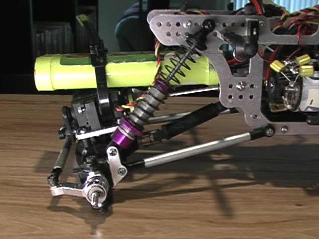
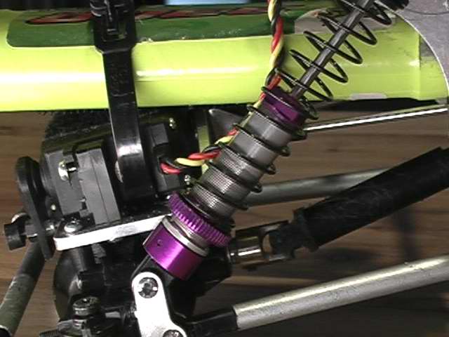
Wow.... lots of drive time in. After reading up on 4-link setups and some observations of the truck climbing over rocks
and stuff, I decided to make some suspension changes. The way the suspension was setup before, was with the upper
and lower links meeting near the same pivot point on the chassis. As seen in this photo:
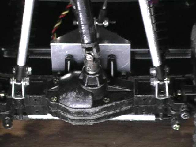
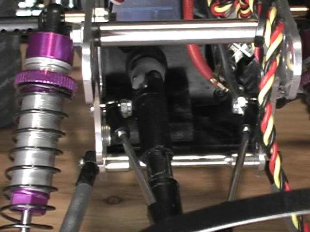
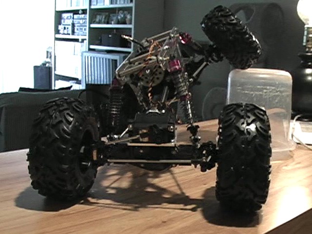
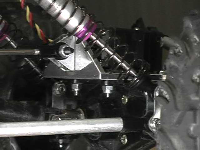
This caused the axles to flex upward, but also in toward the center of the chassis (rotating in an arc). This caused the
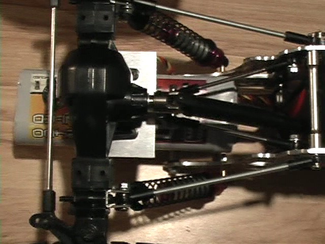
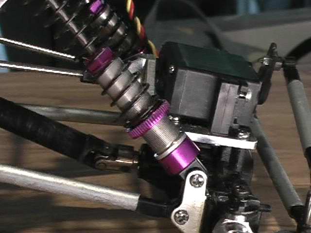
whole truck to cave in on itself during times of high torque. To prevent this, I read that the upper and lower links should be
parallel (when looking from the side). So, I attached the upper links higher up on the chassis. As seen in these photos:
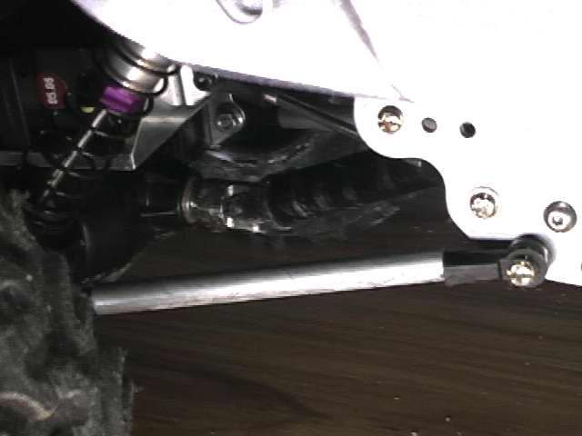
While I was doing this, I also wanted to extend the wheelbase out another 1/4 inch to 12.50 inches. So I fab'd up another
set of lower links and link sleeves and put them on the truck. Doing this, however, caused the shocks to lay down quite a bit
more which pulled the tension off of the springs. Luckily, with the threaded shocks, I was able to screw the springs down on
the shocks to tighten up the suspension. Also at this time, I had to screw down the left rear spring much more to compensate
for the increased torque twist.
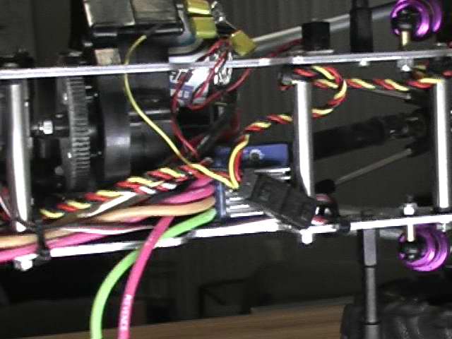
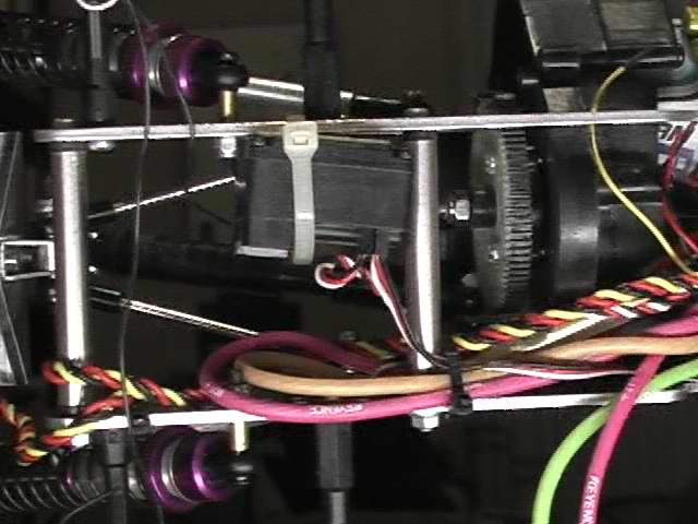
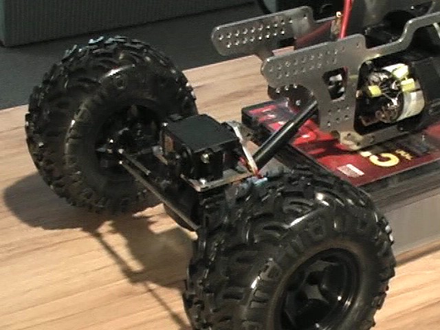
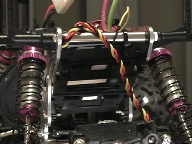
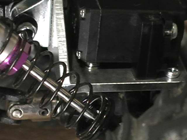
While all the suspension was apart I also had to re-evaluate the location of the electronics. The tray that I used to mount the
receiver and the esc rubbed on the rear drive shaft when the suspension flexed. Also, moving the upper links higher up on
the chassis forced me to remove the try anyway.
Tray in way of rear suspension
|
Rear drive shaft would rub tray
|
So, I ditched the tray and relocated the receiver and esc to the inner sides of the chassis. I mounted the esc in front of the
transmission using double sided tape and I mounted the receiver behind the transmission using double sided tape and a zip
tie.
So, everything is put back together and the performance of the truck is greatly improved. The truck can fully flex and still
maintain its overall length. This has helped the truck climb over obstacles with greater ease.
New stats:
- Wheel Base: 12.50 inches
- Chassis Clearance: 2.88 inches
- Differential Clearance: 1.50 inches
- Width (outside wheel): 10.75 inches
- Weight (with electronics, battery, and body): 5.80 pounds
|
(5-10-2006)
A few weeks ago, a bunch of us socal crawlers got together for a little friendly run. We went to an area in the santa clarita area and
had a blast. You can find a bunch of videos linked here.
After hanging out with the SoCal guys, I was amazed at how long their batteries lasted. I went through 3 batteries while
some of the guys were still on their first. Clearly, my charger and battery were not cutting it. I immediately hit the rccraweler forums and
searched for battery and charger discussions. I was using a 15min fast charger from 1999 and a battery from that same time. Now,
I am using a peak charger and a 3300 nimh battery.
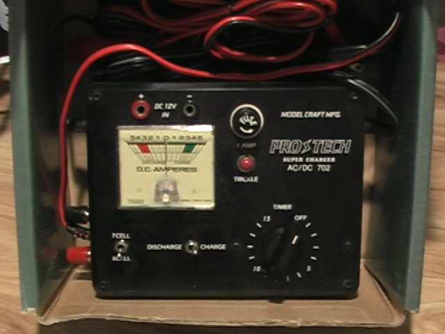 Old charger
|
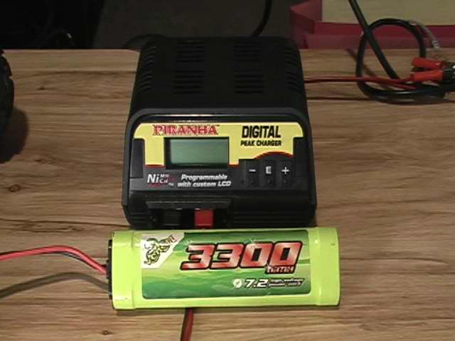 New charger and battery
|
Wow.... now I can run over 3 hours on a single charge and the power from this new battery makes the truck incredibly punchy
and torque-y.
After quite a few runs on the truck, I noticed that it was getting very dirty, sqeeky, and operating rough. So, I took apart all of the
suspension and axles and proceeded to clean it all. I cleaned off all the sand, dirt, and grime and oiled all the suspension joints.
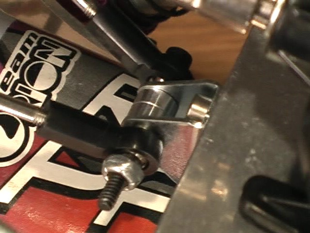
During this time, I also decided to deal with the how the servo plates attached to the axles. Originally, the servo plates were attached
to the axle by 2 screws at the front part of the plate. The rear part of the plate had 2 holes that 2 little plastic pins that were supposed
to come up and poke through. Unfortunately, the holes in the plate didnt quite match the position of the pins and the plate was always
at an angle. Also, during articulation and steering, the plate would bend up and put a lot of pressure on the 2 screws at the font of the plate.
So, I cut off the 2 plastic pins and drilled holes in the plastic arms that went right under the holes in the servo plate. I was then able
to use screws to mount the rear of the plate to the axle.
 2 screws/nuts under servo plate
|
 2 screws/nuts under servo plate
|
 Screw on rear of servo plate visible under servo
|
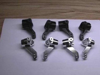
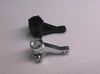
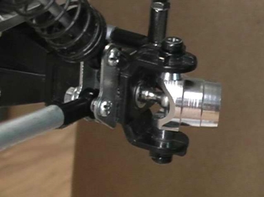
Another problem.... after so many runs on the truck, the arms on the knuckles are getting very worn. In addition, the arm on the
rear knuckle is bending about 15 degrees when the rear tires are digging in and I try to steer the truck. Sooooo.... I went ahead and
picked up some aluminum knuckles.
 arm that bends
|
 worn arm
|
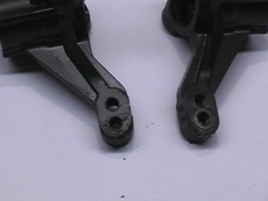 worn arm
|
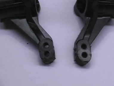 worn arm
|
New aluminum knuckles.
New aluminum knuckles on truck.
While I was replacing the knuckles I also decided to replace the bushings with bearings. However, I had to wait a week for them
to come in. They finally did come in and now the truck is finally, fully re-assembled. Now I have to find some time to go out and do
some crawling...
(5-21-2006)
Wow.... I got another great day of crawling in. I took my video camera along and did some recording. I then edited it; threw in
some music, fades, text, etc... Here it is (~70mb)
From this crawling, I noticed some more imperfections with the handling (man, I am never going to be done with this thing).
From the video, you can see this one rock that I kept trying to get up. Every time, the right front wheel would come up off
the rock and then the truck would roll over. What was happening is that the left rear of the suspension would flex and the front end
would come up (torque twist). Also, I think the high center of gravity contributed to the rolling over. So..... the first thing that I did
was flip the shocks over and then increase the tension on the rear shocks. Flipping the shocks puts the shock head that is filled
full of oil lower down on the truck. This may not be much weight, but every little bit helps to lower the center of gravity.
 Front shocks flipped
|
 Rear shocks flipped
|
 Front spring tension loose
|
 Rear spring tension tightened
|
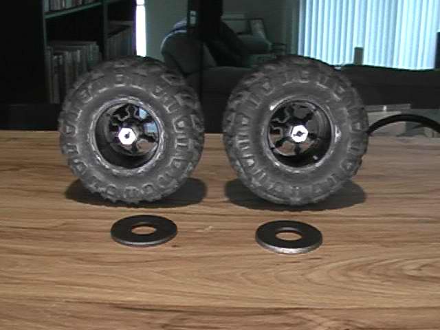
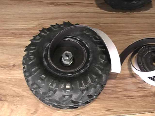
Next, I decided to add weights to the front wheels. Since the tires are already glued to the wheels, I could not put any weight on the
inside of the tire. So I had to opt for adding weight to the inside of the wheel. I read alot about using automotive wheel weights
on the inside of the wheels for weight, but I was not able to find any auto parts store that sold wheel weights. So, I had to come
up with another solution. I hit home depot and found a couple of large, heavy washers and glued them to the inside of the wheel.
 Looking at inside of wheel
|
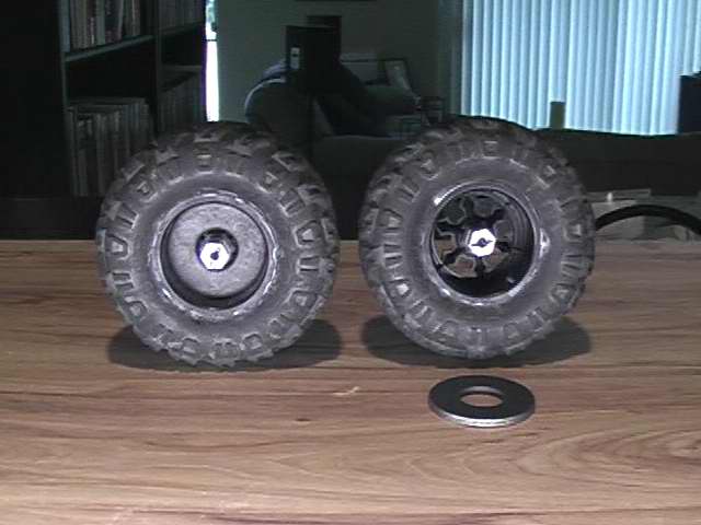 Washer glued to inside wheel
|
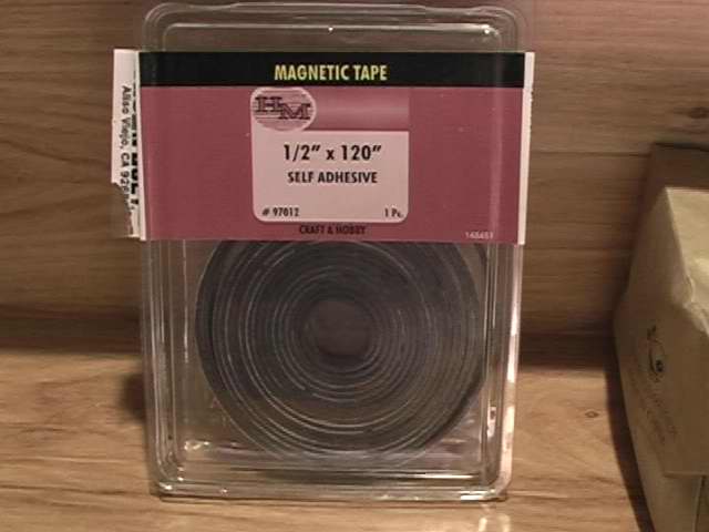
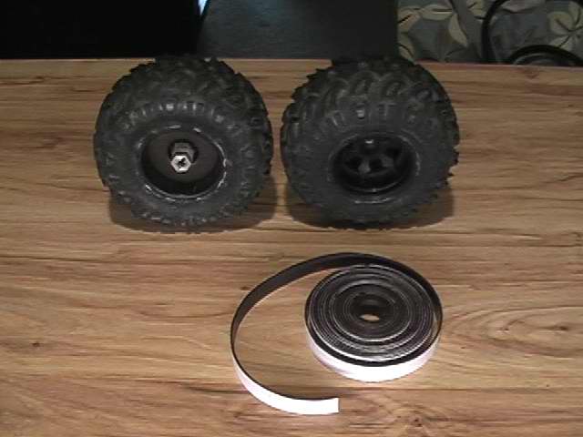
Then I took self adhesive magnetic tape and wrapped it around on the inside of the wheels. (I know, I thought about the magnetic
interference that might occur with the electronics and motors on the truck. So I wrapped the entire truck with the tape and drove it
around and there was no interference).
|
|
 Wrapped around once
|
 Wrapped around twice
|
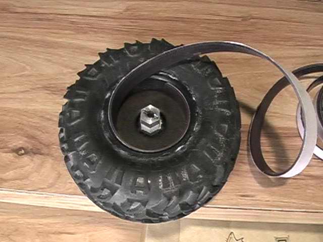
I also used glue to make sure that the tape would stay on the wheel. The tape also holds the washer in place very nicely and
is also flush with the edge of the wheel. Here are the complete wheels with weights:
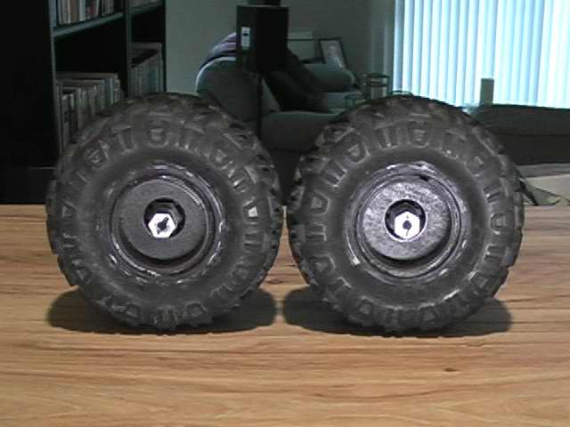 Inside of wheels
|
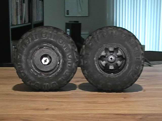 Inside and outside of wheels
|
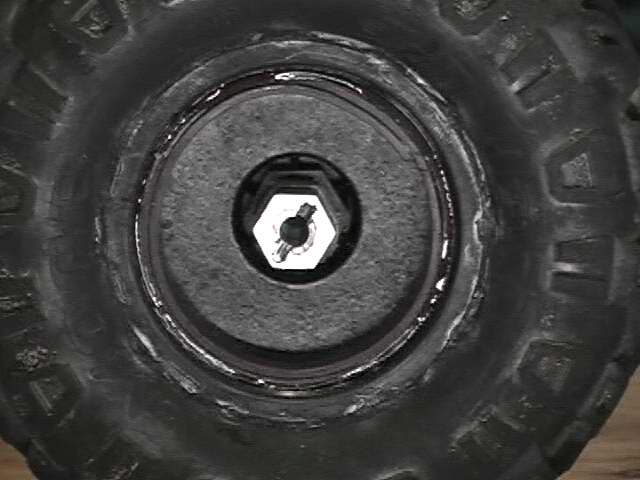 Inside close up
|
 Inside on truck
|
Each washer cost $0.07 and the package of tape was $4.00.
Here are the numbers on adding the wheel weights for each tire/wheel
- Original tire/wheel weight: 3.2 ounces
- Washer weight: 1.6 ounces
- Tape weight that was used: 1.6 ounces
- New weight of each tire/wheel: 6.4 ounces
- New weight of truck: 6.0 pounds
|
This process doubled the weight of the front tire/wheel. If I wanted more weight, there is still plenty of room to keep
wrapping the tape around the inside of the wheel. (The total weight on the roll of tape was 6.4 ounces.) With an additional
3.2 ounces of weight added to each front wheel, the truck feels much heavier and you can feel the lower center of gravity. The
front servo, however, seems like it is working harder. Hopefully, I wont have to go to a stronger servo. If I do, I may have to go
to a better speed control that can handle the additional amp draw of a more powerful servo (I am using 2 servos split off of
1 output). I took the truck out side and breifly climed around on some rocks. The truck seem much more planted to the ground
and the front end really digs in and flexes alot. I will have to go out to that same steep rock and try to climb it to see how it goes...
|